
Blog
How is the selection of phototherapy LED chips, incoming material inspection, and board testing carried out step by step?
I. Selection of LED chips and incoming material inspection
1. Requirements for LED chip selection
LED chips are the core light-emitting components in phototherapy devices; their output spectrum, radiative power, temperature characteristics, and reliability directly determine treatment efficacy, photobiological safety, and the overall devices compliance. When selecting components, evaluation should be conducted across four key dimensions: application requirements, parameter specifications, component qualification, and long-term reliability:
1.1 Spectral and Optical Parameter Selection
- Center wavelength and half-width: Match the target clinical treatment wavelength bands of the product (e.g., 630 nm/660 nm/850 nm/940 nm, etc.) and specify the permissible tolerance range;
- Radiation flux and radiation illuminance: Calculate the output of each individual LED, taking into account the layout of the lamp board and the optical structure, to ensure that the target irradiance on the working surface of the complete unit meets the requirements specified in the specification document;
- Beam angle: The lens/reflector structure is designed accordingly to prevent localized irradiance from exceeding permissible limits and to ensure that irradiance uniformity meets the required standards, thereby mitigating the risk of photobiological hazards under IEC 62471.
1.2 Selection of Electrical and Thermal Characteristics
- Matched to the rated voltage, rated current, drive mode (current-mode priority), and drive circuit configuration;
- Thermal resistance parameters: evaluate the junction temperature during prolonged continuous operation, control the upper limit of the LED junction temperature, and prevent spectral drift and accelerated light decay during long-term operation;
- Forward voltage consistency: Control the Vf dispersion within the same batch to prevent excessive differences in the brightness and power of the LED chips on the lamp board.
1.3 Reliability and Environmental Adaptability Selection
- Operating temperature range, storage temperature, resistance to moisture and heat, and resistance to cyclic temperature shock; these should be compatible with the overall equipment operating environment;
- Failure mode: Prioritize packaging solutions with low failure rates; consider the electrostatic discharge (ESD) sensitivity level and implement an ESD protection solution for the associated production line.
1.4 Requirements for Component Qualification and Compliance Documentation
- Supplier qualifications, specifications, and factory test reports;
- Material declarations under the Restriction of Hazardous Substances Directive (RoHS), the Registration, Evaluation, Authorisation and Restriction of Chemicals (REACH) Regulation, and other related instruments;
- If UL is involved: verify that the LED itself has a UL certification file and that the plastic packaging housing meets the UL 94 flame retardancy rating; ensure that the complete device complies with UL structural and flame-retardance requirements;
- Assess the completeness of the documentation to prepare the list of materials required for subsequent IEC and UL certification of the complete equipment.
2. Incoming Inspection of LED Chips
Upon receipt of the LED chips, IQC (Incoming Quality Control) conducts incoming inspection in accordance with the inspection specifications, distinguishing between visual inspection, electrical testing, optical inspection, packaging inspection, and documentation verification; the sampling plan is implemented based on the AQL (Acceptable Quality Limit) or the internal quality plan:
2.1 Document Verification: Verify the material number, batch number, specification sheet, and Certificate of Conformity (COC)/test report; confirm that the model matches the sealed sample; and verify that the flame-retardant and material declaration documents are complete.
2.2 Visual Inspection: The encapsulant should be free of bubbles, cracks, yellowing, or contamination; the pins should show no oxidation, deformation, or signs of cold solder joint; markings should be clear; and the wire harness should be free of damage, material reversal, or material shortages.
2.3 Random Inspection of Electrical Parameters: forward voltage Vf measurement (at rated current) and reverse leakage current Ir measurement; calculate batch dispersion and discard materials that exceed the specified tolerance limits; during the inspection of ESD-sensitive LED beads, personnel must wear an anti-static wristband and use an anti-static work surface.
2.4 Random Inspection of Optical Parameters: Conduct testing on an integrating sphere or optical test platform to determine the central wavelength, spectral curve, and radiant flux; verify that these values fall within the specified tolerance limits, with particular emphasis on controlling wavelength shift, as wavelength drift directly affects treatment efficacy and the results of IEC 62471 photobiological safety testing.
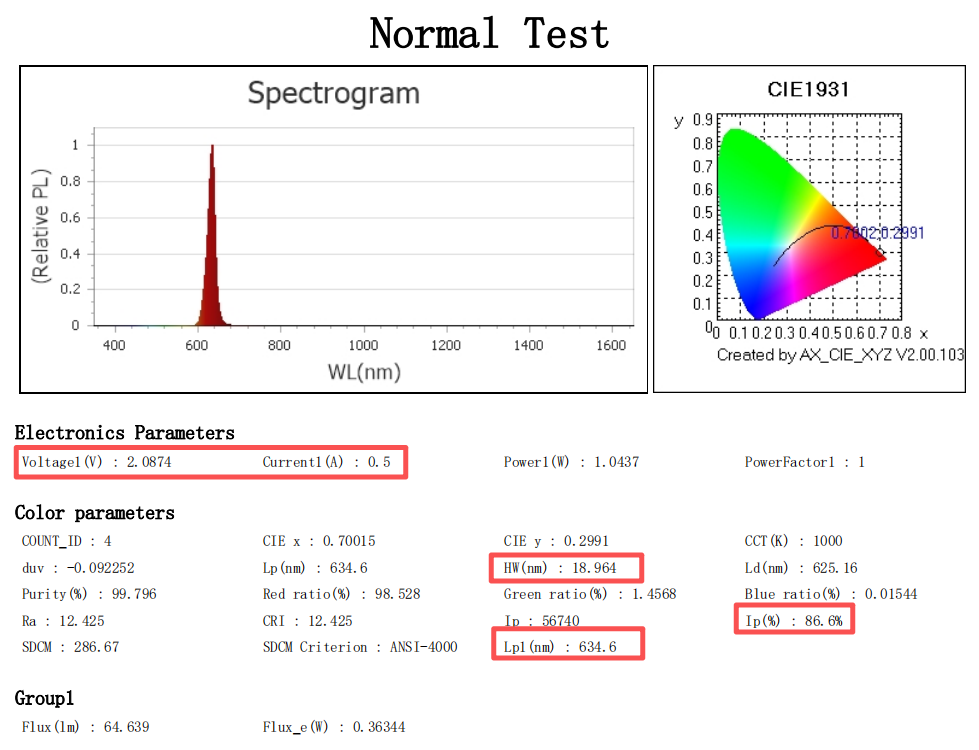
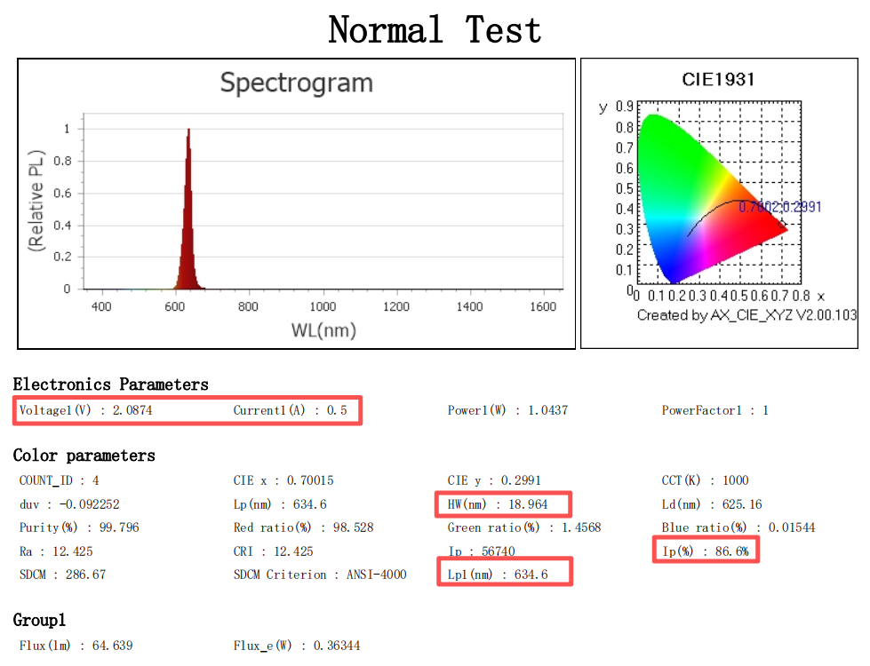
Figure 1: Integrated Sphere Test Report for 630 nm LED Chip
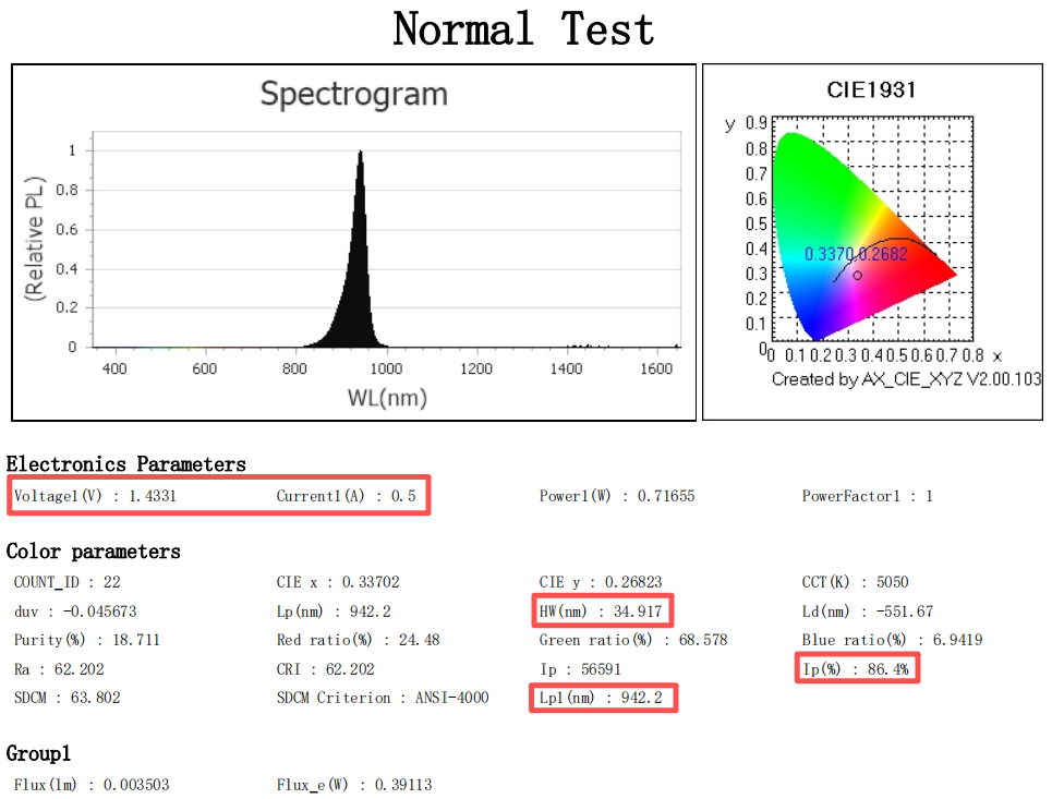
Figure 2: Integrated Sphere Test Report for 940 nm LED Chips
As shown in the test report for the integrating sphere, we first check whether the voltage at the rated current matches the value specified by the supplier; next, we examine the IP value (photometric saturation ratio, Photoelectric Saturation). An IP value of 30%–90% indicates that the curve fitting for this test is acceptable; finally, we inspect the wavelength and half-width (HW; full standard designation: FWHM = Full Width at Half Maximum) of the LED chip. Taking a 630 nm wavelength LED chip as an example, the permissible wavelength tolerance is ±5 nm; a half-width ≤ 25 nm is considered acceptable for a substandard LED chip. For LED chips, a smaller HW indicates purer light output, more precise wavelength, and better monochromaticity. A smaller HW is therefore an important indicator of LED chip quality and the level of expertise of the light source manufacturer.
2.5 Handling of Nonconforming Items: For incoming materials that are nonconforming, follow the nonconforming-product procedure: isolation and review (special acceptance / return); for special acceptance, the impact on optical performance, safety, and certification testing must be assessed and documented.
II. Testing of the lamp panel after assembly
The lamp board is an assembly comprising LED chips, a PCB, and drive circuitry/current-limiting components; it consists of two stages: a cold-state initial test (immediately after power-on operation) and a thermal stability test (after thermal equilibrium has been reached).
1. Test immediately after the lighting panel begins operation (cold-start test; during the initial power-on period, typically within 0–5 min after power is applied)
The cold-test represents the initial state of the lamp board and is used to identify assembly and welding defects, reverse polarity of LED chips, cold solder joints, short circuits, failure of individual LED chips, and early failure; it also records the initial reference optical parameters:
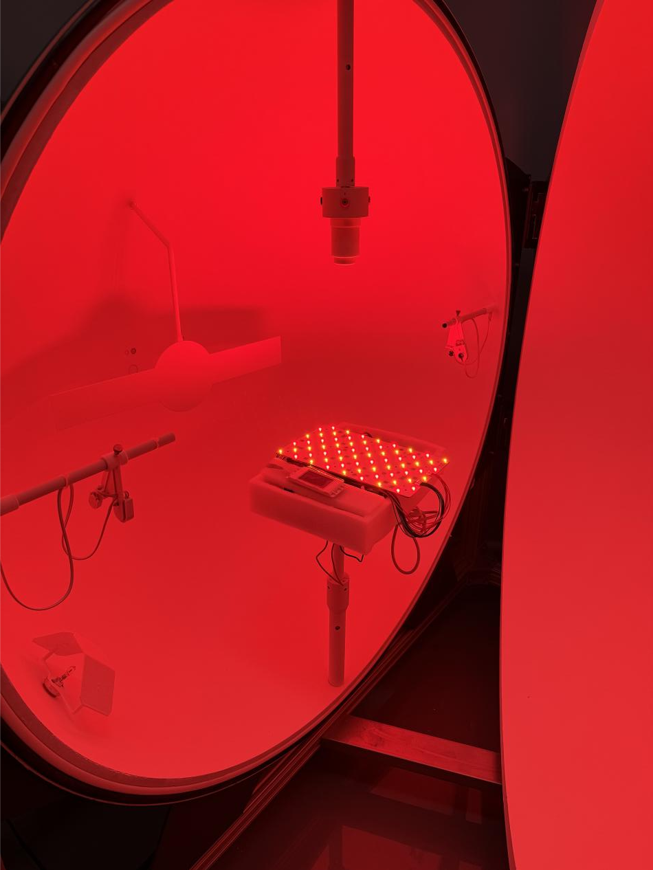
Figure 3: Test setup of the lamp panel with a integrating sphere
- Power-On and Electrical Inspection: After powering on, conduct a visual inspection: all LED beads should illuminate normally, with no dead LEDs, flickering, or localized failure to light; there should be no sparking, abnormal odors, or abnormal heating of the PCB.
- Electrical Testing: total input voltage, input current, and input power; assess the balance of currents in each branch and investigate any abnormal branch current-limiting conditions.
- Optical Benchmark Testing: Record the total panel radiant flux, working-face irradiance uniformity, spectral curve, and peak wavelength; these cold-state initial values shall serve as the baseline for subsequent thermal drift comparisons.
- Basic Safety Preliminary Inspection: Conduct a preliminary inspection of insulation, assess whether the PCB copper layers and wiring pose any short-circuit risk, and verify whether the grounding points are reliable (refer to IEC 60601-1 safety regulations).
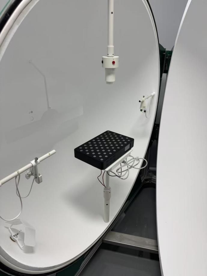
Figure 4: Test diagram of the companys GY-RLT64 integral sphere (not activated)
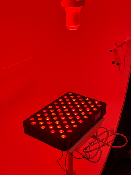
Figure 5: Test diagram of the companys GY-RLT64 integral sphere (startup)
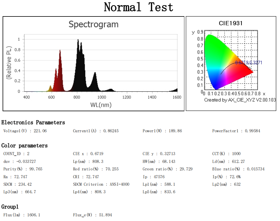
Figure 6: Test report for GY-RLT64 after 1 min of operation (all channels enabled)
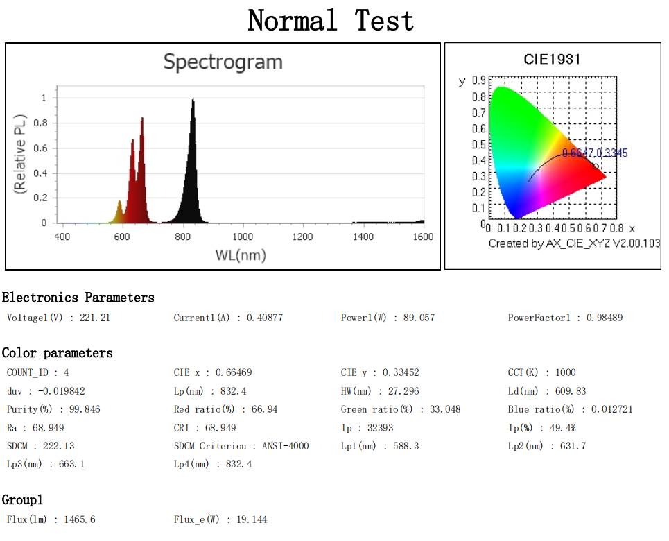
Figure 7: Test report for GY-RLT64 after 1 min of operation (channels at 590 nm, 630 nm, 660 nm, and 830 nm enabled)
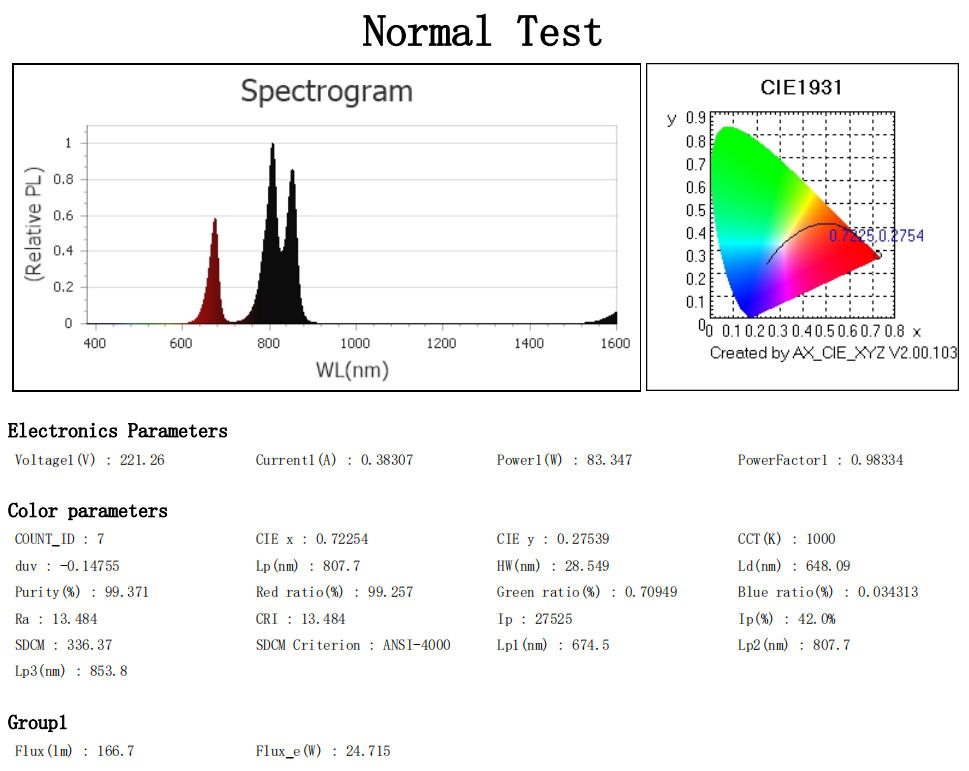
Figure 8: Test report for GY-RLT64 after 1 min of operation (channels at 670 nm, 810 nm, and 850 nm enabled)
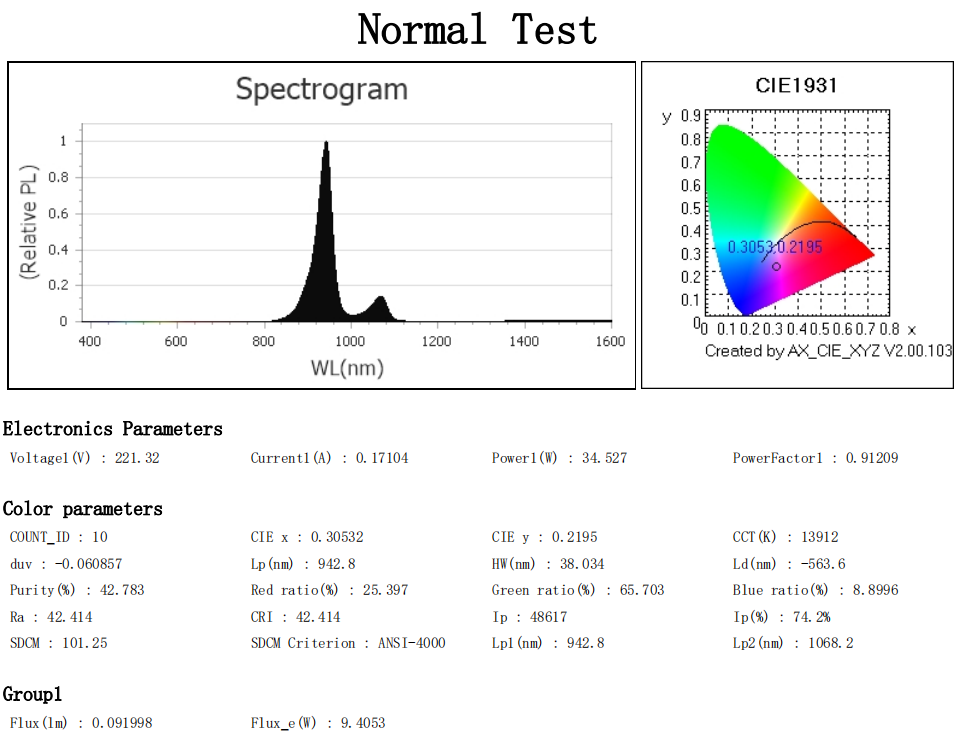
Figure 9: Test report for GY-RLT64 after 1 min of operation (940 nm and 1060 nm channels enabled)
2. Testing after thermal stability has been achieved for the lamp board (thermal equilibrium test: continuous power supply until the temperature stabilizes, typically 30 min~2 h)
When a light source operates continuously for an extended period, temperature rise leads to an increase in junction temperature, changes in Vf, spectral shift, power degradation, and irradiance attenuation; moreover, many tests under UL and IEC standards are conducted under steady-state operating conditions, making thermal stability testing of paramount importance:
2.1 Temperature Monitoring: Use thermocouples to measure the PCB temperature, the LED substrate temperature, and the LED housing temperature; record the maximum steady-state temperature; and assess whether the temperature rise meets the device specifications and the accessible surface temperature rise limits specified in the overall equipment safety regulations (IEC 60601-1).
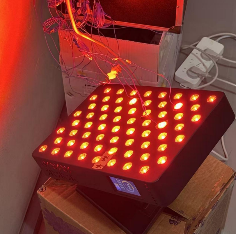
Figure 10: GY-RLT64 thermocouple temperature acquisition
2.2 Steady-State Electrical Testing: Measure the steady-state input current and power; compare these values with the cold-state data; calculate the power reduction ratio; and determine whether any abnormal drift is present.
2.3 Steady-State Optical Testing: Re-measure radiant flux, irradiance, and spectrum; calculate optical degradation/parameter drift; and focus on monitoring wavelength shift—excessive wavelength shift not only affects treatment output but also alters the results of the photobiological safety assessment (IEC 62471).
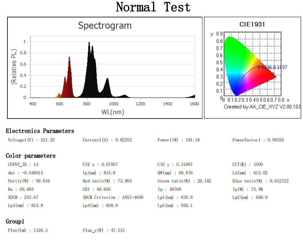
Figure 11: Test report for GY-RLT64 after 30 min of operation (all channels enabled)
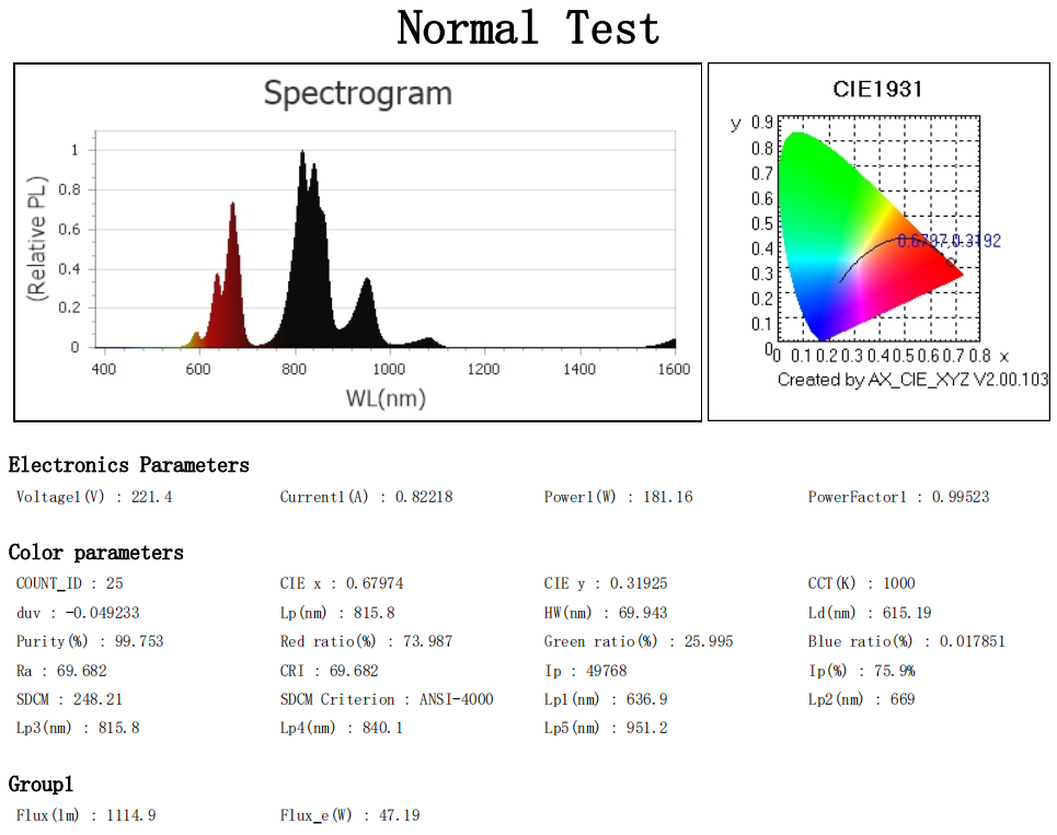
Figure 12: Test report for GY-RLT64 after 60 min of operation (all channels enabled)
2.4 Long-term stability observation (optional durability pre-test): Subject the device to continuous power-on aging and observe whether any LED beads gradually go out, flicker, or exhibit continuously deteriorating parameters; this allows design defects in soldering, heat dissipation, and driver design to be exposed in advance.
2.5 Failure Criteria: If steady-state parameters exceed specification tolerances, temperature rise exceeds the allowable limit, or dead lights/flickering occur, the unit is deemed non-compliant; a review of the heat dissipation structure, drive scheme, and LED selection is required.
III. Analysis of the Lamp Board Test Results
3.1 Analysis of Electrical Test Results
| Runtime(min) | mean power (W) | Power reduction ratio (relative to the cold state) |
| 1 | 189.9 | — |
| 30 | 181.2 | 4.6% |
| 60 | 181.1 | 4.6% |
Interpretation of the electrical test results: A power decrease of 4.6% is within the normal range. The underlying mechanism is that an increase in junction temperature causes the forward voltage drop Vf to decrease; under constant-current drive, this manifests as a synchronous reduction in input power—power decreases rather than increases—which serves as further evidence that the drive scheme employs a constant-current source and that the design is correct. The power change from 30 min to 60 min is only 0.1 W, indicating that the entire unit has reached thermal equilibrium and stabilized within 30 min and will operate stably over extended periods.
3.2 Analysis of Optical Test Results
| Runtime (min) | Mean wavelength: 1 nm | Mean wavelength: 2 nm | Mean wavelength: 3 nm | Mean wavelength: 4 nm | Mean wavelength: 5 nm | Mean wavelength: 6 nm | Mean wavelength: 7 nm | Mean wavelength: 8 nm | Mean wavelength: 9 nm |
| 1 | 588.3 | 631.7 | 662.9 | 674.6 | 807.7 | 832.4 | 853.4 | 942.5 | 1068.1 |
| 30 | 591.8 | 635.0 | 666.6 | 676.9 | 812.6 | 838.2 | 857.3 | 946.8 | 1074.4 |
| 60 | 590.7 | 634.1 | 665.7 | 676.5 | 811.2 | 836.5 | 856.6 | 946.1 | 1073.3 |
Optical result drift (relative to operation for 1 min)
| Runtime (min) | Wavelength 1 drift (nm) | Wavelength drift: 2 nm | Wavelength 3 drift (nm) | Wavelength drift: 4 nm | Wavelength drift: 5 nm | Wavelength drift: 6 nm | Wavelength drift: 7 nm | Wavelength drift: 8 nm | Wavelength drift: 9 nm |
| 30 | 3.5 | 3.3 | 3.7 | 2.3 | 4.9 | 5.8 | 3.9 | 4.3 | 6.3 |
| 60 | 2.4 | 2.4 | 2.8 | 1.9 | 3.5 | 4.1 | 3.2 | 3.6 | 5.2 |
Optical test results indicate that the trends fully align with expectations: the longer the wavelength (GaAs-based), the faster the drift; AlGaInP visible-light devices with wavelengths between 588 and 675 nm exhibit relatively slow drift. No channel exhibited abnormal drift beyond the physical limits of the material (e.g.,>0.3 nm/℃), indicating the absence of overcurrent-driven LED chips and good thermal design uniformity.
After thermal equilibrium was reached (30 min), the wavelengths in each channel remained within the effective therapeutic window of their respective bands.
At 60 min, all 8 channels and 9 wavelengths have returned by 1.1–1.7 nm (approximately 70% of their respective drift amounts at 30 min), with a highly consistent magnitude of return. When all 8 channels exhibit systematic changes in the same direction simultaneously, the likelihood of random measurement errors is greatly reduced, making a slight, genuine temperature decrease more probable; for example:
- The temperature-control fan accelerates after 30 min, causing the junction temperature to drop by approximately 4–6 °C (corresponding to a drift reduction of 1–1.7 nm, which is consistent in magnitude);
- Ambient temperature and airflow changes result in a slight improvement in heat dissipation conditions.
IV. The Purpose of Conducting UL Certification and IEC Series Standard Testing for Products
“LED chip selection → incoming material inspection → hot and cold-state testing of the LED board” constitutes an internal prequalification activity conducted prior to certification. Its value lies in exposing risks associated with the light source in advance, before the complete unit is submitted for testing, thereby supporting the type testing specified in the following standards.
4.1 UL Certification
- Conduct advance verification of the flame retardancy rating of LED packages and the flame retardancy rating of the PCB substrate to ensure compliance with the UL flame-retardance requirements for the complete device;
- Benchmark the temperature rise test data against UL temperature rise limits to address overheating risks in advance;
- Organize component documentation, BOMs,and supplier information in advance to meet the requirements for UL filing and the review of critical components;
- Inspect PCB routing, insulation, and spacing to avoid non-conformities in the UL structural inspection.
4.2 IEC 60601-1 General Safety for Electrical Equipment
- Lamp board temperature rise data is used for the temperature rise assessment of accessible components;
- Insulation of the lamp board, creepage distance, electrical clearance, and grounding continuity shall be verified in advance during the lamp-board stage;
- Evaluate the margin of the rated parameters of components to prevent the risk of overload, overheating, and fire.
4.3 IEC 60601-1-2 Electromagnetic Compatibility (EMC)
- Current fluctuations in the lamp board driver and constant-current circuit, as well as switching noise, can be observed at the lamp board stage;
- Identify the sources of radiated and conducted interference as early as possible to reduce the likelihood of failure in overall device EMC testing; LED flicker and unstable current are often early indicators of EMC anomalies.
4.4 IEC 62471 Photobiological Safety
This is the most critical specialized standard for the light source in phototherapy equipment; the spectrum, irradiance, light-emitting area, and exposure duration all depend entirely on the steady-state optical data of the lamp panel.
- The spectrum after thermal stabilization represents the equipments true operating spectrum and serves as the input for calculating the photometric hazard classification (hazard-free / Class 1 / Class 2 / Class 3);
- If only cold-state data are measured, spectral drift encountered by the certification laboratory during steady-state testing may lead to a change in the determination of the photobiological safety level, directly resulting in test failure;
- This process controls irradiation uniformity and peak irradiation, thereby preventing localized irradiation levels from exceeding permissible limits and causing excessive photic hazards to the retina and skin.
4.5 IEC 60601-2-57: Safety for Phototherapy Devices
This dedicated standard imposes mandatory requirements on treatment output, irradiation uniformity, output stability, overtemperature protection, and output drift:
- Comparative data between cold and hot states are used to demonstrate the stability of the light source output;
- Verify that the treatment output does not exceed the permissible deviation during prolonged operation;
- Provide empirical data for the design of alarm output, power limiting, and overheat protection logic.
V. For users looking to purchase a phototherapy device: What should you consider when making your selection?
The points discussed above all reflect an industry-specific perspective. For ordinary users, this can actually be simplified into the “four observations”:
First, check whether the “thermal-state value” has been clearly specified. Do not focus solely on the 660 nm and 850 nm values on the nameplate. You can directly ask customer service or sales: “After the equipment has been operated continuously for half an hour, what is its output wavelength?” Brands that can provide measured thermal-state data and have the confidence to include it in their manuals have put genuine effort into the project; those that are only willing to quote a nominal cold-state value should be viewed with skepticism.
Second, examine the drive and temperature-control design. Search the manual for two key terms: “constant-current drive” and “temperature control / overheat protection.” Constant current means that the wavelength and power will not drift as the device generates more heat over time; temperature control means that, after prolonged use, the devices spectral output remains more stable and safer. If you cannot find either term in a product, you can generally conclude that its cost has been cut somewhere in the background.
Third, check whether the test report is based on “third-party + steady-state” measurements. When asking a seller to provide a test report, pay attention to two points: the report must be issued by a third-party institution (rather than being merely a self-test result), and the test conditions must be steady-state data obtained after continuous operation. Reports obtained merely by running the device for a few minutes after cold startup have limited reference value.
Fourth, consider the irradiance and operating distance rather than focusing solely on the power rating. For two devices both rated at 100 W, differences in LED arrangement and lens design can result in irradiance power densities on the skin that differ by several-fold. Whether the manual clearly specifies the “correspondence between operating distance and irradiance” is another indicator of the manufacturers level of expertise.
reference standard
IEC 60601-1:Medical electrical equipment – Part 1: General requirements for basic safety and essential performance.
IEC 60601-1-2:Medical electrical equipment – Part 1-2: General requirements for basic safety and essential performance – Collateral standard: Electromagnetic disturbances – Requirements and tests.
IEC 62471:Photobiological safety of lamps and lamp systems.
IEC 60601-2-57:Medical electrical equipment – Part 2-57: Particular requirements for the basic safety and essential performance of non-laser light source equipment intended for therapeutic, diagnostic, monitoring, cosmetic and aesthetic use.